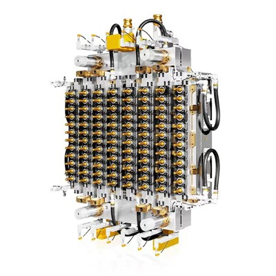


As a supplier of 96 Cavity Preform Molds, I understand the critical role that gate design plays in the overall performance and quality of preform production. The gate is the entry point through which molten plastic is injected into the mold cavity, and its design can significantly impact the filling pattern, part quality, and production efficiency. In this blog post, I will share some insights on how to optimize the gate design in a 96 Cavity Preform Mold to achieve the best possible results.
Understanding the Basics of Gate Design
Before delving into the optimization process, it's essential to have a solid understanding of the basic principles of gate design. The gate size, shape, location, and type all play crucial roles in determining the flow of molten plastic into the mold cavity. Here are some key factors to consider:
- Gate Size: The gate size should be carefully selected to ensure proper filling of the mold cavity without causing excessive pressure drop or flow restrictions. A gate that is too small can lead to incomplete filling, while a gate that is too large can result in excessive flashing and poor part quality.
- Gate Shape: The gate shape can have a significant impact on the flow pattern of the molten plastic. Common gate shapes include round, rectangular, and fan-shaped gates. Each shape has its own advantages and disadvantages, and the choice of gate shape will depend on the specific requirements of the preform design.
- Gate Location: The gate location should be carefully chosen to ensure uniform filling of the mold cavity and minimize the formation of weld lines. The gate should be placed in a location where the molten plastic can flow smoothly into the cavity without encountering any obstacles or restrictions.
- Gate Type: There are several types of gates commonly used in preform molds, including hot runner gates, cold runner gates, and valve gates. Each type of gate has its own advantages and disadvantages, and the choice of gate type will depend on the specific requirements of the preform design and production process.
Optimizing the Gate Design for a 96 Cavity Preform Mold
Now that we have a basic understanding of gate design, let's explore some strategies for optimizing the gate design in a 96 Cavity Preform Mold.
1. Conduct a Flow Analysis
Before making any changes to the gate design, it's essential to conduct a flow analysis using a computer-aided engineering (CAE) software. A flow analysis can help you visualize the flow of molten plastic through the mold cavity and identify any potential issues or areas for improvement. By analyzing the flow pattern, you can determine the optimal gate size, shape, location, and type for your preform design.


2. Consider the Preform Design
The preform design plays a crucial role in determining the optimal gate design. The shape, size, and wall thickness of the preform can all affect the flow of molten plastic and the formation of weld lines. When designing the gate, it's important to consider the specific requirements of the preform design and ensure that the gate is located in a position that will allow for uniform filling of the mold cavity.
3. Optimize the Gate Size and Shape
The gate size and shape should be carefully selected to ensure proper filling of the mold cavity without causing excessive pressure drop or flow restrictions. A gate that is too small can lead to incomplete filling, while a gate that is too large can result in excessive flashing and poor part quality. The gate shape should also be chosen to ensure smooth flow of the molten plastic into the cavity and minimize the formation of weld lines.
4. Choose the Right Gate Location
The gate location should be carefully chosen to ensure uniform filling of the mold cavity and minimize the formation of weld lines. The gate should be placed in a location where the molten plastic can flow smoothly into the cavity without encountering any obstacles or restrictions. In a 96 Cavity Preform Mold, it's important to ensure that the gate location is consistent across all cavities to ensure uniform filling and part quality.
5. Select the Appropriate Gate Type
There are several types of gates commonly used in preform molds, including hot runner gates, cold runner gates, and valve gates. Each type of gate has its own advantages and disadvantages, and the choice of gate type will depend on the specific requirements of the preform design and production process. Hot runner gates are often preferred for high-volume production because they offer better control over the flow of molten plastic and can reduce cycle times. Cold runner gates are more suitable for low-volume production or applications where cost is a major concern. Valve gates offer the best control over the flow of molten plastic and can be used to produce high-quality preforms with minimal flashing.
Case Studies
To illustrate the importance of optimizing the gate design in a 96 Cavity Preform Mold, let's take a look at some real-world case studies.
Case Study 1: PET Preform Mould for Oil Bottles
In this case study, a customer was experiencing issues with incomplete filling and poor part quality in their 96 Cavity Preform Mold for oil bottles. After conducting a flow analysis, we discovered that the gate size was too small, which was causing excessive pressure drop and flow restrictions. We recommended increasing the gate size and changing the gate shape to a fan-shaped gate to improve the flow of molten plastic into the cavity. After implementing these changes, the customer was able to achieve uniform filling and improve the part quality significantly.
Case Study 2: Edible Oil Preform Mold
In this case study, a customer was experiencing issues with weld lines and flashing in their 96 Cavity Preform Mold for edible oil bottles. After conducting a flow analysis, we discovered that the gate location was not optimal, which was causing the molten plastic to flow unevenly into the cavity and form weld lines. We recommended moving the gate location to a more central position and changing the gate type to a valve gate to improve the control over the flow of molten plastic. After implementing these changes, the customer was able to eliminate the weld lines and reduce the flashing significantly.
Case Study 3: Beverage Bottle Preform Mold
In this case study, a customer was experiencing issues with cycle times and production efficiency in their 96 Cavity Preform Mold for beverage bottles. After conducting a flow analysis, we discovered that the gate type was not suitable for their production process, which was causing excessive cycle times and reduced production efficiency. We recommended changing the gate type to a hot runner gate to improve the control over the flow of molten plastic and reduce the cycle times. After implementing these changes, the customer was able to achieve significant improvements in production efficiency and reduce the overall cost of production.
Conclusion
Optimizing the gate design in a 96 Cavity Preform Mold is essential for achieving the best possible results in terms of part quality, production efficiency, and cost. By understanding the basic principles of gate design and using the right tools and techniques, you can optimize the gate size, shape, location, and type to ensure uniform filling of the mold cavity and minimize the formation of weld lines and flashing. If you're interested in learning more about how to optimize the gate design in your 96 Cavity Preform Mold, please don't hesitate to contact us. We'd be happy to discuss your specific requirements and provide you with a customized solution.
References
- Beardsley, J. (2018). Injection Molding Handbook. Hanser Publishers.
- Rosato, D. V., & Rosato, D. V. (2011). Injection Molding Technology. Kluwer Academic Publishers.
- Throne, J. L. (1996). Polymer Rheology in Injection Molding. Marcel Dekker.